
Portfolios of Consulting Projects
CFD Simulation of Explosion
Explosion simulation using CFD is a very difficult problem due to issues such as extreme scale differences between the whole domain and the reaction region, shock waves, rapid changes in physical quantities before and after the explosion, complex chemical reactions, and the need for large-scale computing capacity due to high-resolution grids and small time intervals.
NEXTFOAM has developed an efficient CFD code for explosion analysis that addresses these challenges. It employs an octree-based unstructured compressible solver incorporating third-order ENO spatial discretization techniques, level set, ghost fluid, and chemical reaction capabilities. To overcome the extreme scale difference, the code employs anisotropic adaptive mesh refinement (AMR) to efficiently manage the number of mesh. Additionally, a dynamic load balancing feature has been developed to enhance parallel computing performance and improve computational efficiency.
The code has been validated through 2D Riemann problems, confined rate stick explosions, and open-field explosion analyses.
Air Pollutant Diffusion CFD SaaS Development

The spread of air pollution plays an essential role in many fields, including air quality improvement, public health, public policy, and urban planning. By implementing the CFD analysis environment as a SaaS service on the public digital twin platform(LX), we maximized utilization and accessibility, and fused sensor measurement data with simulation data.
The scope of development was as follows
- Automatic generation of CAD data of terrain, buildings, and near-surface structures of the target site
- Linking meteorological information to improve the accuracy and reliability of results by incorporating real weather information into simulations
- Automatic mesh generation and simulation execution, enabling SaaS deployment of simulations without specialized knowledge
- Visualization of 3D simulation results Developed cloud infrastructure design to run rendering engine
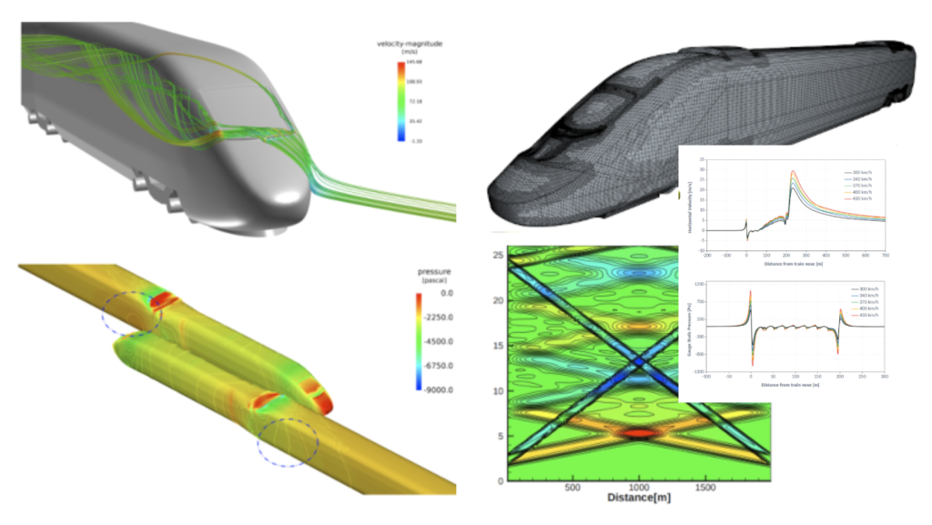
Multi-disciplinary Design Optimization of High Speed Train

This is a study on the optimal design of the front end shape to optimize the aerodynamic performance of next-generation high-speed trains.
Using Bezier curves and surfaces, we derived a shape model and 27 shape parameters that can simulate the front end of a typical high-speed train.
500 sample cases were analyzed with buoyantSimpleNFoam to create a surrogate model, and multi-objective optimization was performed for multiple objective functions such as drag, micro pressure wave and rolling moment using NSGA-II technique.
Create Aerodynamic DB of Grid Fin

To build an aerodynamic database for grid fins used in reusable launch vehicles, we developed a program to automatically generate geometry and point system for meshless CFD, FAMUS and automated the CFD analysis process.
The aerodynamic DB was built through DOE-based analysis point selection, flow analysis, surrogate model creation, and verification. FAMUS was used for the flow analysis and the entire process was built into one framework.
Image-based Measurement of Store Motion
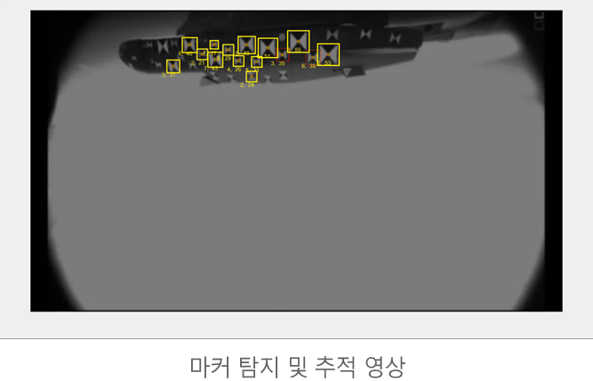
A technique that uses markers on the surface of an object to be dropped and then uses the markers to track the dropped object. It detects markers attached to the target surface, matches the ID of each marker, and manually positions or removes markers as needed. By matching the marker extraction results in the video with a three-dimensional marker model, the position and attitude of the dropped object can be measured, and the behavioral measurement results can be converted to relative motion with respect to a specific coordinate system (e.g., fuselage).
By applying this technology, it is possible to augment virtual geometry, and it is possible to augment virtual structures in a specific space photographed using a drone, including indoor measurement results, as shown in the following figure.
Cavitation Simulation
Cavitation is a phenomenon in which a phase change occurs within a fluid due to a change in pressure caused by a change in the velocity of the fluid. Cavitation is most common in areas where the flow velocity changes significantly, such as nozzles or valves in pipe flows, or around moving objects such as pumps, propellers, etc. Numerical modeling of cavitation is of interest in many fields because the bubbles generate noise or vibration when they dissipate and cause erosion when they hit walls.
We analyzed a variety of problems including hydrofoils, axial pumps, turbo pumps, plunger pumps, super-cavitation, and marine propellers.
Image-based Measurement of High-Speed Rotor Blade

Measuring the behavior of high-speed rotating bodies has been a challenge with traditional contact metrology sensors, but recent advances in camera hardware and image processing technology have made contactless video measurement possible. The measurement system consists of a camera and a synchronous strobe light, with stereo cameras to improve the accuracy of coordinate measurements, and the following example analyzes the displacement of a rotating rotor blade.
The center points of the markers in the left and right images are quickly calculated, and then the dimensional coordinates are restored by 1:1 marker matching. Using the coordinates of the restored markers from 500 images per second and a predefined marker model of the blade surface, the relative displacement was calculated and the rotation angle and pitch angle of the rotor blade per section could be calculated.
Optimization of CFD Workflow

When performing a CFD analysis of a product or system, you will need to decide how much to simplify the geometry, how to configure the lattice, what physical model and numerical methods to use, and what post-processing to perform. You will establish these methods based on your own experience, review of previous studies, and various tests.
Once the analysis method is established, the next important step is to establish the entire workflow efficiently. Especially when the work is handed off to others, when a large amount of calculations are required for geometry optimization or database construction, or when similar problems need to be solved over and over again, workflow becomes a very important issue, not only in terms of efficiency but also in terms of consistency of results.
Simulation of Stack Effect
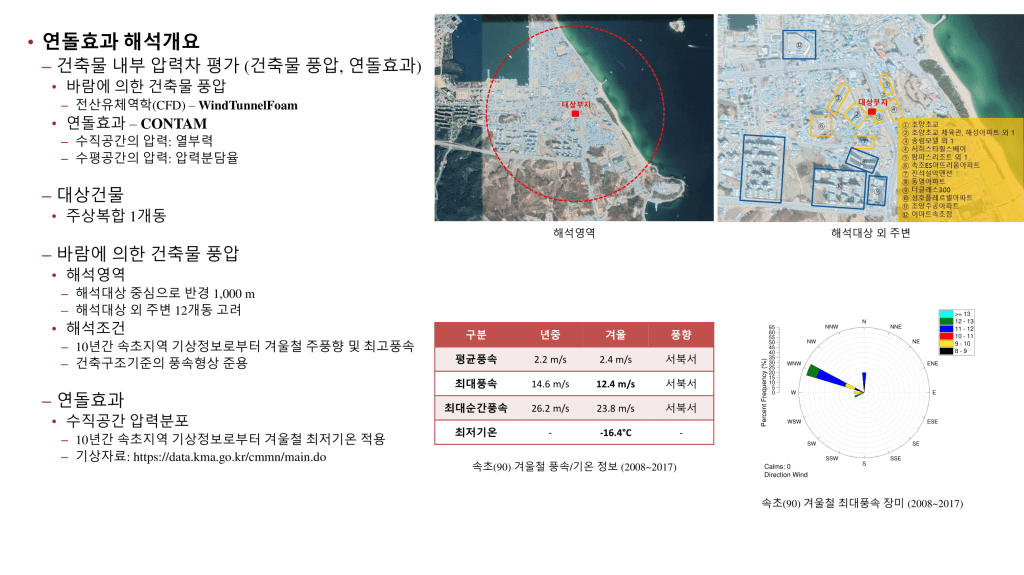
Stack effect is a phenomenon where the air inside a building rises due to the temperature difference between the inside and outside of the building, also known as the “chimney effect”. This can cause elevator doors to malfunction, noises around the doors, cold rooms in the lower floors of the building, and unbalanced heating and cooling in the building.
To analyze the chimney effect, it is necessary to calculate the pressure difference inside the building. To calculate the wind pressure in the building, CFD analysis was performed using WindTunnelFoam developed by NEXTFOAM based on OpenFOAM to derive the wind pressure coefficient, and the analysis conditions were based on meteorological analysis data.
The CONTAM code, a network method developed by NIST, was used to calculate the hail effect. By analyzing the kite effect according to weather conditions, we predicted the point where the problem is expected to occur and proposed a mitigation plan.
Automated Interface for Airframe CFD and Design Integration

Automated the entire process of aerodynamic analysis, which is the core of airplane development, and developed an integrated interface with the design framework.
To automate the analysis process, we developed modules to automatically generate airframe shapes using parameters, automatically generate surfaces and mesh, set up solvers for calculations, and post-processing.
Missile DATCOM was used for shape parameters, OpenCASCADE for shape generation, and Salome for mesh generation, and the solver can optionally use OpenFOAM, meshless code FAMUS, in-house code, or commercial code. ParaView macros are used to automatically generate images of post-processing, and aerodynamic DB is generated in SQL and csv file formats for integration with design frameworks.
The integrated GUI provides functions such as parameter input, job monitoring, 3D/2D image viewer, etc. and the integrated CLI allows each module to be executed in Python.
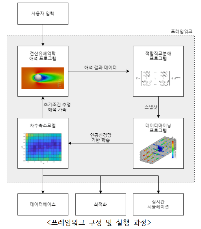
Development of Hybrid Domain(1D+3D) Analysis Code for Hyperloop

Hyperloop systems, which are being touted as the next generation of transportation systems, involve capsules traveling at high speeds inside very long tubes. In the long tube sections in front of and behind the capsule, the flow is almost one-dimensional in nature, while around the capsule, complex compressible turbulent flow occurs in three dimensions.
Based on these physical characteristics, we developed a hybrid domain analysis technique that uses a combination of one- and three-dimensional domains to achieve both accuracy and efficiency in the analysis. Data is transferred based on the average or profile) of physical quantities at the boundary between the 1D and 3D domains.
This method can extend the computational domain to a very large area, while saving computational resources and greatly reducing the analysis time by performing three-dimensional precise analysis only in areas that require complex analysis. The developed hybrid domain analysis technique can be utilized for similar system analysis.
Aerodynamic Analysis of High Speed Train
We have performed aerodynamic analysis using CFD for all high-speed trains in Korea, including G7, KTX, KTX Sancheon, HEMU, EMU, and Hypertube. The aerodynamic characteristics of high-speed trains have a significant impact on stability and ride comfort as well as energy efficiency through resistance reduction, so it is very important to analyze and analyze them accurately.
The aerodynamic analysis of high-speed trains is very challenging due to the very long vehicle length, complex vehicle geometry, compressible flow characteristics, and non-stationary calculations using dynamic mesh. It requires a lot of computational resources and time, so it is important to determine the level of simplification of the geometry and model without compromising accuracy.
Some of the major projects undertaken include: aerodynamic drag in open areas and tunnels, crosswind stability, effects of train winds, micro pressure waves in tunnels, side forces due to cross-passing, 1D/3D hybrid analysis in tunnels, optimization of frontal geometry, and analysis of climate control systems.
Development of Specialized Preprocessing Program

CFD consists of pre-processing, computation, and post-processing. The most cumbersome and human time-consuming of these is pre-processing, which consists of creating geometry, generating mesh, and setting up computational conditions. Pre-processing, especially geometry creation, is often the most difficult part of CFD analysis, especially if you are not an expert in analysis. Learning a separate 3D CAD program for CFD is a daunting task, and while it is best to automate geometry creation with parameters, this is often not possible.
For these people, the best approach is to develop a pre-processing program that embeds a simple CAD program specialized for the specific application. For modeling the geometry around an air conditioner outdoor unit, we developed a specialized pre-processor with the necessary CAD functions and automatic mesh generation using snappyHexMesh.
Pre-processors specialized for a specific problem are a great way for non-CFD experts to directly use simulation in design or after-sales service.
Simulation of Heat Transfer Rollers

A heat transfer roller is a piece of equipment used in the film and printing industry and various machining processes, which is used to heat or maintain the temperature of a product or material using heat transfer through a fluid. The effect of a small gap between the outer shell and baffle of a hot water roll on its heat transfer performance was analyzed through three-dimensional CFD analysis.
The effects of the rotation of the hot water roll on the flow and heat transfer of the hot water stream, the effect of the direction of the inlet and outlet of the hot water stream on the heat transfer when there is a gap between the outer shell and the baffle, and the effect of the number of revolutions of the baffle pitch were examined. The conjugated heat transfer (CHT) analysis was performed to consider the conduction of solids, and the MRF method was used for the rotation of the rolls.
Program Development to build an Aerodynamic DB for airplanes

In airplane design, accurate estimation of aerodynamic coefficients is essential. To build aerodynamic DB based on CFD simulation, we developed an automated framework and GUI program for building aerodynamic DB based on surrogate model. By modeling the response of the real model at a relatively low cost, the surrogate model technique can significantly reduce the cost/time required for DB construction and derive aerodynamic coefficients for any continuous combination of conditions outside the experimental point.
Building an surrogate model requires multiple layers of work, including DOE-based analysis point selection, flow analysis, surrogate model generation, and validation, but by integrating these disparate tasks into a single framework, work efficiency and scalability can be achieved.
The CFD analysis was performed using FAMUS, a meshless program. Meshless method is easy to automate the pre-processing using a parameter-based operation to shorten the work time, and it is robust and flexible even in the situation of wing or fin deflection.
For five variables, including Mach number, AOA, bank angle, and deflection angle of two fins, we derived appropriate analysis points and built and verified the aerodynamic DB by creating a Kriging model.
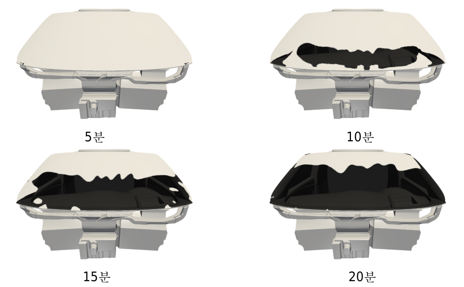
Automated CFD Program Development for Print Leveling
We have developed a dedicated program that automates the entire process of geometry creation, mesh generation, analysis, and post-processing for print leveling CFD analysis.
It reads 2D design drawings in pixel form and modifies them to create 3D geometry. OpenCASCADE, an open source 3D modeling library, is used to create the geometry and SALOME, an open source mesh generation tool, is used to create the 3D surface mesh. blockMesh is used to construct the volume mesh and the 3D surface mesh is used to set the initial conditions for the leveling paste. Simulate the final geometry using the VOF multi-phase flow solver for dynamic contact angles, surface tension, viscosity, and other conditions.
Automated post-processing, including data, image, and animation extraction.
CFD Program Development for Tunnel and Platform

We have developed a program for various CFD analyses required for tunnel and platform design. It consists of the following modules
- Fire Spread Module: A program for simulating the spread of a fire inside a tunnel, calculating critical velocity and thermal buoyancy.
- Platform Screen Door (PSD) module: a program to analyze the wind pressure on the platform screen door.
- Micro-pressure Wave Module: A module for analyzing the micro-pressure wave as the train progresses by modeling tunnel entrances and exits and ventilation openings in three dimensions and the rest in one dimension.
- HVAC module: A general-purpose program that can calculate platform air conditioning and tunnel outflow airflow reentry
CFD Solver Development for Defrosting
To simulate the defrosting of an automobile cabin, a conjugated heat transfer solver and a solidification/melting model that considers heat transfer through solids (glass) were used.
The conjugated heat transfer solver provided by OpenFOAM solved the problem by reducing the relaxation factor and using a technique with a large diffusion that significantly compromised the accuracy. We improved the solver algorithms (pressure-velocity coupling, interpolation technique, relaxation factor dependence, time step dependence) and modified the slope limiter, pressure gradient discretization method, turbulence generator linearization method, etc. The results of the developed solver were compared and validated with the results of commercial codes.
Customized CFD Program Development for Heat Exchanger

A multi-region solver was developed to calculate the conjugated heat transfer of fluids and solids in the hot and cold regions of a heat exchanger.
Since modeling the fin structure of the heat exchanger as it is in the CFD domain is still costly, the fin structure was modeled using porous media method. The energy equation calculation in porous media used the dual cell method, which superimposes the cold and hot regions so that heat transfer occurs between the two regions in the same geometric position.
We developed a script to convert the commercial code mesh and split it into multi-region so that the analysis case can be automatically configured, and developed a heat transfer model and GUI for porous media. Validated the results against the commercial code and verified that the inlet and outlet temperature values agree within 1%.
Developed a function to map the calculated solid region temperatures for use in CALCULIX, an open-source structural analysis program, and used the mapped results to perform structural analysis in CALCULIX.
CFD Program Development for Dispensing

A solver was developed and validated to analyze the dispensing process. The VOF method was used for the multi-phase flow simulation and the overset method for the nozzle movement. The development included the following topics
- Modeling variable viscosity properties, implementing a temperature-dependent viscosity model: Implementing a temperature-dependent viscosity model using an Arrhenius type power law for non-Newtonian fluid simulation
- Improved handling of gravity flux on the wall: In dispensing simulations, the air pressure between the liquid and the substrate rises before the liquid touches the substrate, preventing the liquid from reaching the surface of the substrate. The flux is obtained by interpolating the velocity component with the gravity term removed to the grid plane and adding the gravity flux component obtained directly from the grid plane.
- Dynamic contact angle: When using a static contact angle, the shape varies greatly depending on the grid size, so we used a dynamic contact angle. Improved grid dependency by implementing Navier slip length as a logarithmic function of the height of the first grid.
- Overset related feature improvements: The inverse distance method, an overset interpolation technique, has a problem when the overset area encroaches on the boundary of the background grid, which we solved by increasing the resolution of the virtual grid.
- Developing Overset Setup Scripts and Utilities
- Developed a mesh automation utility
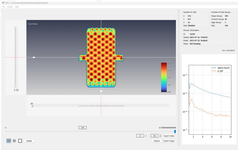
POD and ANN-based ROM Framework Development for Real Time Simulator
We developed a framework to generate CFD ROM based on POD and ANN. The framework consists of OpenFOAM for CFD, AccelerateCFD for POD, and DAKOTA for data mining, and the execution and data exchange of each program is automatically executed in parallel with minimal user intervention.
The developed framework has the potential to significantly improve productivity in all areas of CFD analysis-based development by automating the process of data mining of analysis results and drastically reducing the time required for analysis, while laying the technical foundation for its application to optimization or digital twin problems that require a large amount of computation.
For data exchange between the programs at each stage of the framework, interlocking programs are developed to convert the input and output formats of each program to each other. As a result, the programs in the framework are automatically executed in a series when the user inputs only minimal parameters such as the purpose of execution and analysis conditions, so that the progress and final output results can be easily checked on the framework, and the resulting data files can be easily obtained.
A program was developed to generate post-processing files for the CFD program analysis results, POD results, data mining and optimization process so that the user can check the results visualized as contours/charts, etc.
The developed frame was verified by applying it to the free surface wave internal tidal wave problem and the airfoil shape optimization problem.
For the free surface wave internal tidal wave problem, an artificial neural network reduced order model and database were created by setting the input variables as the size of the tidal wave region (two variables for depth and width) and the output variable as one variable for the root mean square deviation of the surface wave height.
The airfoil optimization sought to find the optimal value of the camber parameter that maximizes the lift ratio while keeping the airfoil thickness and angle of attack fixed among the parameters. A script was written to automatically generate an OpenFOAM grid from the airfoil geometry parameters, and the geometry parameters were plugged into the framework as input. We set the framework’s execution objective to reduced-order model-based optimization (maximum value search) and ran it, and it converged to the maximum value after about 496 calculations.
Configure Automatic Parameter-based Geometry-Flow coupling Framework for UAM

Using CAD files generated by the Unmanned Vehicle Parametric Geometry Automation Framework, automation modules for mesh generation and CFD were developed.
The CFD analysis uses an OpenFOAM-based solver developed by NEXTFOAM. The rotation of the propeller was performed using an actuator disk model to obtain results in a short time. A post-processing module is included to automatically extract the pressure field, forces acting on each module, and aerodynamic coefficients from the calculation results.
The geometry file consists of propeller, boom, fuselage, spinner, motor, canard, wing, etc. and automatically sets the surface grid size and feature edge extraction options for each part.
The analysis conditions are input from an excel file, including flight conditions (speed, angle of attack, angle of deflection), rotor characteristics for actuator disk application (Cp, Ct, lift direction), and calculation conditions (number of iterations, result storage interval, number of parallel computation cores).
The entire process of grid generation – flow analysis – post-processing is executed in a single Python script.
Turbulence model Development for High Accuracy Wave Generation
When performing wave-generating CFD simulations using the RANS turbulence model, wave decay occurs, where the wave height gradually decays over the simulation time. To address this issue, Density-modified and Buoyancy-modified models that account for free water buoyancy effects were developed and applied to the standard k-epsilon, realizable k-epsilon, and SST k-omega models.
The Density-modified method is a turbulence model that compensates for density-induced effects that are canceled out due to the strict incompressible assumption in OpenFOAM when analyzing incompressible multi-phase flows, while the Buoyancy-modified method is a turbulence model that adds a buoyancy term caused by density gradients in addition to the Density-modified method.
To verify the developed model, two-dimensional regular wave (Stokes 5th) analysis and circular cylinder wave run-up analysis among three-dimensional regular waves were performed, and it was confirmed that the wave height attenuation phenomenon was effectively suppressed.
Design Program Development for a Marine Propeller Appendage to Reduce Sound Level
We developed a program to automate the process of mesh generation, CFD analysis, and post-processing of ships with vortex generators to quickly and easily check the effect of various variables on the design of vortex generators.
The hull geometry is represented by a CAD file. The appendages are automatically designed in the program according to the design parameters (size, shape, attachment location, angle of attack) specified by the designer, and the linear information of the ship with the designed appendages is output in a form that can be used in the ship design program used by the linear designer.
The mesh generation uses snappyHexMesh and the analysis solver uses simpleNFoam developed by NextFoam.
The turbulence model uses the Quadratic strain Reynold stress transport model (NEXT::RSM_QS).
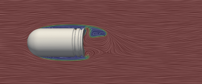
Vortex Shedding Simulation of a Riser
This is the result of a three-dimensional cylinder vortex shedding analysis using the DES turbulence model.
Surge and sway motions are supported by elastic springs and the rest of the motion is constrained.
- solver : pimpleDyMNFoam, openfoam5
- turbulence model : dynamicKEqn & kOmegaSSTDES
- Re = 3900 & 6.7e+5